- Welcome to Brown instruments (Jiangsu) Co., Ltd official website!

Product Overview
Float-type level gauges feature simple construction, convenient commissioning, and high reliability. Widely applicable across petroleum, chemical, power, water treatment, food, pharmaceutical, papermaking, metallurgy, marine, and boiler industries, these gauges measure liquid levels or interfaces in high-temperature, high-pressure, viscous, contaminated, flammable, explosive, and corrosive media.
The core operating principle of the float-type level gauge is based on Archimedes' principle of buoyancy and magnetic coupling technology. As the liquid level within the container changes, the internal float containing a magnet rises or falls. Through magnetic coupling, this movement drives the magnetic components (such as reed switches or magnetoresistive sensors) within the external measuring conduit to change state. This results in the output of switch signals or continuous standard analog signals like 4-20mA, enabling liquid level measurement and control. Key advantages of this gauge include ease of maintenance, high safety, and cost-effectiveness, with particular suitability for challenging conditions like viscous fluids, high temperatures/pressures, and contaminated environments .
Float-type level gauges are primarily categorized into switch types (outputting discrete signals) and continuous measurement (transmitter) types (outputting continuous signals). Installation methods are flexible and diverse, including top vertical mounting, side mounting, bottom mounting, and bypass pipe mounting, to accommodate different vessel structures and measurement requirements.
Limitations of float-type level gauges include: sensitivity to changes in medium density; presence of mechanical moving parts susceptible to wear over extended use; measurement blind zones at the top and bottom; and potential interference with the float or linkage in applications where the medium is prone to scaling or adhesion.
With technological advancements, float-type level gauges are evolving toward intelligent, high-precision, and multifunctional designs. For instance, integrated microprocessors enable self-diagnosis and calibration, while wireless transmission facilitates remote monitoring. New materials enhance corrosion resistance and high-temperature tolerance, allowing operation in more extreme conditions.
Working Principle
Float-type level gauges operate on the buoyancy principle of liquids acting upon magnetic floats, fundamentally based on Archimedes' principle and magnetic coupling technology. An internally magnetized float rises and falls with the liquid level, driving magnetic components within the measuring tube via magnetic coupling. When the magnetic element reaches specific positions, its magnetic field triggers reed switches or alters the state of magnetic resistance sensors, Hall effect sensors, etc., converting liquid level changes into electrical signal outputs. The displacement of the magnetic float with liquid level variations is converted through a signal conversion mechanism to output either switch signals or continuous analog signals (e.g., 4-20mA). It features stable and reliable operation without requiring adjustment. It enables display, alarm, and control of medium liquid levels in open, closed containers, or underground tanks from the instrument control room. Detectable media include conductive and non-conductive liquids such as water, oil, acids, alkalis, and industrial wastewater, while overcoming false level indications caused by liquid foam. Float-type level gauges are widely used in industries including petroleum refining, chemical processing, papermaking, food production, and wastewater treatment.
Product Structure
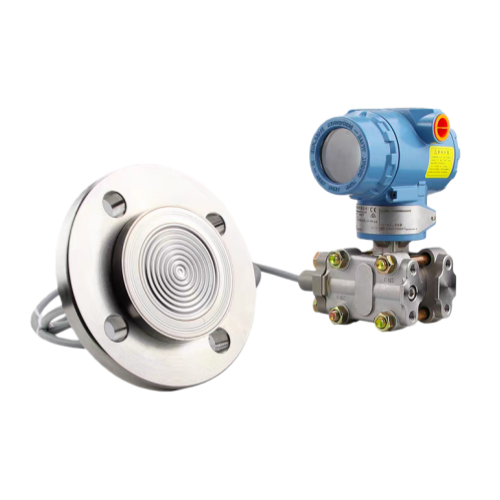
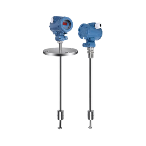
Float-type level gauges primarily consist of three structural components: buoyancy device, connection/conversion device, and display device. The buoyancy device corresponds to the float within the gauge, typically made of stainless steel or engineering plastics. Material selection should be 304 or 316L grade. The probe, float, and process connection components of the float level gauge should be made of PP or PTFE. Available materials include stainless steel, polypropylene, and polytetrafluoroethylene. The connection and conversion device specifically adopts a lever-type structure, where the float is connected to a magnetic assembly (moving magnet) inside the measuring tube via a connecting rod or lever mechanism [7]. Display devices incorporate magnetic reed switches, precision resistors, and amplification conversion circuits. Magnetic float level gauges (level switches) are primarily designed based on buoyancy and static magnetic field principles. The magnet within the float interacts with the sensor (magnetic reed switch) to output a resistance value signal. Alternatively, a transmitter module can be integrated to output a current value signal (4–20mA).
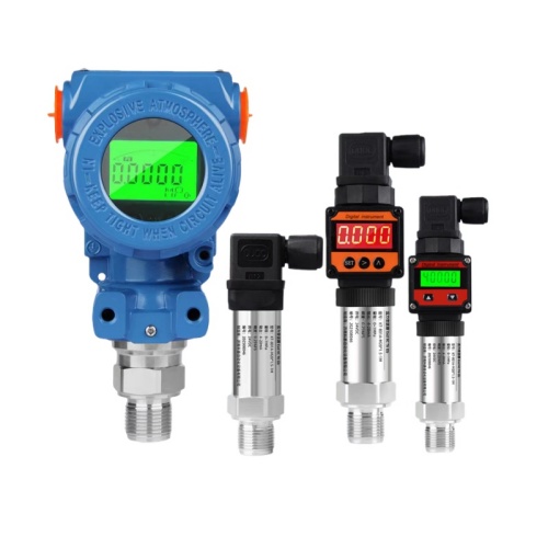
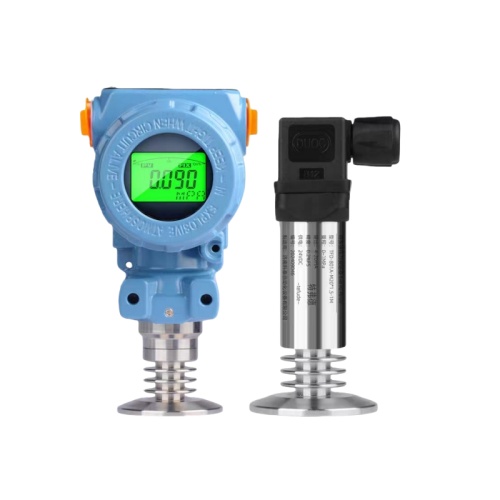
Float level gauges can be categorized into two types based on sensor design: soft-cable float level gauges and rigid-rod float level gauges. Installation methods further classify them into various configurations: top-mounted, bottom-mounted, side-mounted, etc. Bypass pipe installation effectively mitigates interference from deposits adhering to the main vessel wall. By function or output signal: - Level switches output an ON/OFF signal. - Level transmitters (continuous measurement) output a continuous standard current or voltage signal proportional to the current liquid level. - Magnetic float level switches (level switches) can output switch signals. - Level gauges can directly output resistance value signals or, when paired with a transmitter module, output current value (4–20mA) signals.
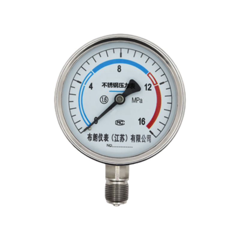
Common technical parameters for float-type level gauges include measurement range, operating pressure, and medium temperature. The measurement range typically spans 300–6000 mm, with rated operating pressure generally ≤1.6 MPa and maximum capacity up to 16.0 MPa. The medium temperature range is generally -20 to 125°C, with some models offering -40 to 550°C. Medium density must be ≥0.5 g/cm³ or ≥0.65 g/cm³, and medium viscosity is typically required to be ≤0.05 Pa·s. Output signals include switch signals, 4–20 mA analog signals, and HART protocol, with a common supply voltage of 24 V DC. Protection rating is typically IP65, with explosion-proof rating up to ExdⅡCT6Gb.
Operation and Maintenance
Installation
The float level gauge must be installed vertically to ensure free vertical movement of the float assembly within the main tube. It is recommended to install a shut-off valve between the vessel and the gauge to isolate the material during cleaning or maintenance. Magnetic conductors must not be present near the main tube, as they directly impair normal operation. Install away from feed inlets to prevent false readings caused by turbulence. When the measurement range exceeds 3 meters, consider adding intermediate reinforcement flanges or supports for structural integrity. The measured liquid's specific gravity must exceed that of the float, and the medium should contain no ferromagnetic impurities. Install in a location where the float's vertical movement is unobstructed. The core wire cross-sectional area of cables connecting the remote level transmitter to secondary instruments must exceed 0.8mm². When laid parallel to AC power lines, maintain a minimum distance of 20 cm; separate conduit installation is recommended.
Commissioning and Operation
After installation, calibration with a magnet is required. Guide the flip-column mechanism once to ensure red indicators below zero and white indicators above zero. During startup, first open the lower dip tube valve to allow the liquid medium to enter the main tube steadily. This prevents the liquid medium from rapidly lifting the float assembly, which could cause the flip-columns to malfunction or flip erratically.
Operation and Troubleshooting
Common malfunction “abnormal indication” may result from detached float balls, broken float linkage, damaged float conversion mechanism, or faulty float pointers/dial faces. Troubleshoot sequentially and replace corresponding components. If the float level transmitter suddenly loses indication with no signal in the measurement circuit, the dial face may be damaged and requires replacement. Common fault “Magnetic Field Interference” occurs when strong magnetic fields exist near the gauge or container, or when measured liquids contain magnetic impurities. This can disrupt normal operation or demagnetize components. Promptly eliminate interference sources. Common fault “Float Jammed” typically results from impurities and contaminants in the measured liquid causing buildup on the guide rod. Regularly inspect and clean the guide rod and float surface.
Maintenance and Care
Depending on the medium conditions, periodically open the bottom drain flange or remove the drain screw to flush sediment from the main tube with clean water. For liquids containing impurities, regularly clean the float and guide rod to prevent jamming. Online calibration and testing can be performed without disassembling the level gauge. Using proper instruments and methods, on-site calibration and testing of measurement accuracy, stability, and other performance characteristics can be conducted. This primarily includes zero calibration, range calibration, linearity testing, and repeatability testing. Daily maintenance should focus on preserving instrument labels and other components to avoid damage. Unless necessary, avoid using isolators to protect the instrument. If isolator use is required, ensure proper selection.
Common Faults and Solutions
Troubleshooting for float-type level gauges follows the principles of regular maintenance and symptom-based diagnosis.
Indicator malfunctions are common, manifesting as maximum readings, low readings, or no indication. Possible causes include float detachment, broken float linkage, damaged conversion mechanism, or instrument head failure. Solutions involve inspecting and replacing damaged components, and cleaning the guide rod and float.
Magnetic field interference may cause instrument malfunction or component demagnetization. Causes include strong magnetic fields near the instrument/vessel or magnetic impurities in the measured liquid. Remedy: Inspect and eliminate strong magnetic fields; verify absence of magnetic impurities in the liquid.
Float jamming typically occurs due to impurities or scaling in the medium, preventing free float movement or signal output. Shut down the system to clean the float and guide rod surfaces. For liquids containing impurities, regularly clean the instrument guide rod.
Transmitter signal fluctuations may result from poor signal line connections or electromagnetic interference. Inspect signal line connections and eliminate electromagnetic interference.During preventive maintenance and selection, note that this level gauge is unsuitable for liquids containing suspended impurities or paramagnetic substances, as these may cause jamming. Installation must ensure no strong magnetic fields nearby and placement away from feed inlets to prevent false readings.