- Welcome to Brown instruments (Jiangsu) Co., Ltd official website!

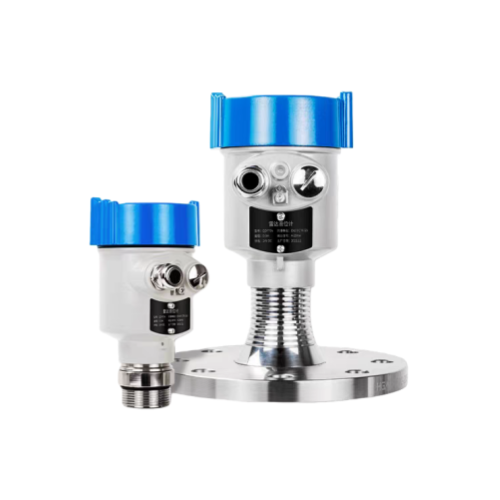
Product Overview:Brown Company's 76-81GHz Radar Level Transmitter is a radar measurement product utilizing the Frequency Modulated Continuous Wave (FMCW) principle. It is widely applicable for measuring distance, material height, volume, weight, and open channel flow in liquids, slurrie
Product Overview:
Brown
Company's 76-81GHz Radar Level Transmitter is a radar measurement
product utilizing the Frequency Modulated Continuous Wave (FMCW)
principle. It is widely applicable for measuring distance, material
height, volume, weight, and open channel flow in liquids, slurries, and
viscous substances. It can also measure solid media such as powders,
granules, and bulk materials. Stable measurements are achievable even in
dusty or agitated applications. Supports both two-wire and four-wire
configurations. The product offers a maximum range of 120m with a
minimum dead zone of 0.08m. Its higher operating frequency and shorter
wavelength make it particularly suitable for solid applications.
Utilizing a lens antenna for transmitting and receiving electromagnetic
waves, it delivers unique advantages in high-dust environments and
extreme temperatures up to +200°C.
Working Principle:
The
general principle of the FM continuous-wave radar level gauge is that
the radar emits electromagnetic waves on the top of the tank and the
electromagnetic waves are received by the radar after being reflected by
the medium.
The frequency difference δf between the received
signal and the transmitted signal is proportional to the distance R from
the surface of the medium: R=C (speed)*δf (frequency difference)/2/K
(frequency modulation slope).
Because the speed of light C and
the frequency modulation slope K are known, the frequency difference δf
can be estimated to obtain the distance R from the radar installation
position to the material surface, and then through the known total
height of the tank, subtract the spatial distance from the radar to the
material surface (referred to as Empty height) to get the height of the
material level.
Product Features:
• Utilizes transmission frequencies up to 76-81GHz, enabling a more compact RF architecture and higher signal-to-noise ratio.
• 5GHz operating bandwidth delivers superior measurement resolution and accuracy, suitable for metrology applications.
• Narrowest 3° antenna beam angle concentrates energy for enhanced interference resistance and reliability.
•Minimized measurement blind zones deliver superior performance even in small tanks.
• Shorter wavelengths enhance reflection characteristics for fine-grained media and inclined surfaces.
•
Features high measurement sensitivity, rapid refresh rates, compact
antenna size, simple installation, rugged durability, and
maintenance-free operation.
• Non-contact measurement eliminates wear and contamination, enabling liquid and solid media detection.
•Utilizes
two-wire loop powering technology, transmitting both supply voltage and
output signal through a single two-core cable for cost savings.
•
Employs advanced microprocessors and unique echo processing technology,
suitable for various complex operating conditions. Virtually unaffected
by temperature, pressure, water vapor, dust, and other challenging
environments.
• Features extremely low transmission power, enabling
installation in various metal and non-metal containers without harm to
human health or the environment.
• The display with buttons allows for convenient setting of the instrument's parameters.
Technical Specifications:
| Measurement principle | 2/4-wire, FMCW radar | Shell window | polycarbonate |
| Frequency range | W-band [76-81GHz] | Ground terminal | Stainless steel |
| Maximum operating distance | +/-0.5%(Standard) | Cable inlet/plug | 1 blind plugged M20×l.5/1 M20 XL.5 cable inlet |
| Measurement accuracy | ±1mm/±3mm | terminal | The cross section of the wire is 2.5mm² |
| Output form | 4~20mA,RS-485 | Fault signal | The current output is unchanged;21mA;3.6mA |
| Communication mode | HART,MODBUS | Integration time | (0 to 20)s, adjustable |
| Power supply range | 24VDC OR220VAC | Measuring interval | About 1 second (depends on parameter Settings) |
| Antenna form | Horn or lens antenna | Adjustment time | About 1 second (depends on parameter Settings) |
| Process joint | Flanges from DN50, threads from G3/4 | Relative humidity | ˂ 95% |
| Process pressure | -1…20 bar | shock-proof | Mechanical vibration l0m/s², (10 ~ 150)Hz |
| Process temperature | -40~+200℃ | Class of protection | IP67 |
| Ambient storage temperature | -40~+80℃ | Explosion-proof class | ExdiaIICT6 |
| shell | Cast aluminum/stainless steel | Installation mode | Threaded or flanged |
Installation Notes:
When
the antenna transmits microwave pulses, it emits within a specific
angle. No obstructions should be present within the microwave radiation
zone—defined as the area between the lower edge of the threaded
connection or flange and the surface of the measured medium. Therefore,
installation should avoid internal silo fixtures such as ladders, limit
switches, heating equipment, and supports whenever possible. Failure to
do so may cause measurement errors. Additionally, ensure the microwave
radiation zone does not intersect with the material flow during filling.
If necessary, perform “false echo learning” when the silo is empty.
During installation, note that the maximum material level must not enter
the instrument's measurement blind zone, and a minimum distance must be
maintained between the instrument and the silo wall. Install the
instrument so the antenna's transmission direction is as perpendicular
as possible to the surface of the measured medium. Avoid installation
locations subject to vibration.
Recommended Installation Location
Install
at a position between 1/4 and 1/3 of the silo diameter, maintaining a
minimum horizontal distance of 200mm from the silo wall. Failure to do
so may result in erroneous readings. Avoid installation in environments
with strong vibrations. For flat-topped or conical tanks, mount the
radar level gauge at the exact center of the top to ensure the
transmission angle covers the tank bottom.

Common Installation Errors
Ensure no obstructions (e.g., ladders, steps) are within the beam path, as shown below:

Instrument
installation must position the antenna beam away from the feed inlet
and perpendicular to the material surface, as illustrated below:

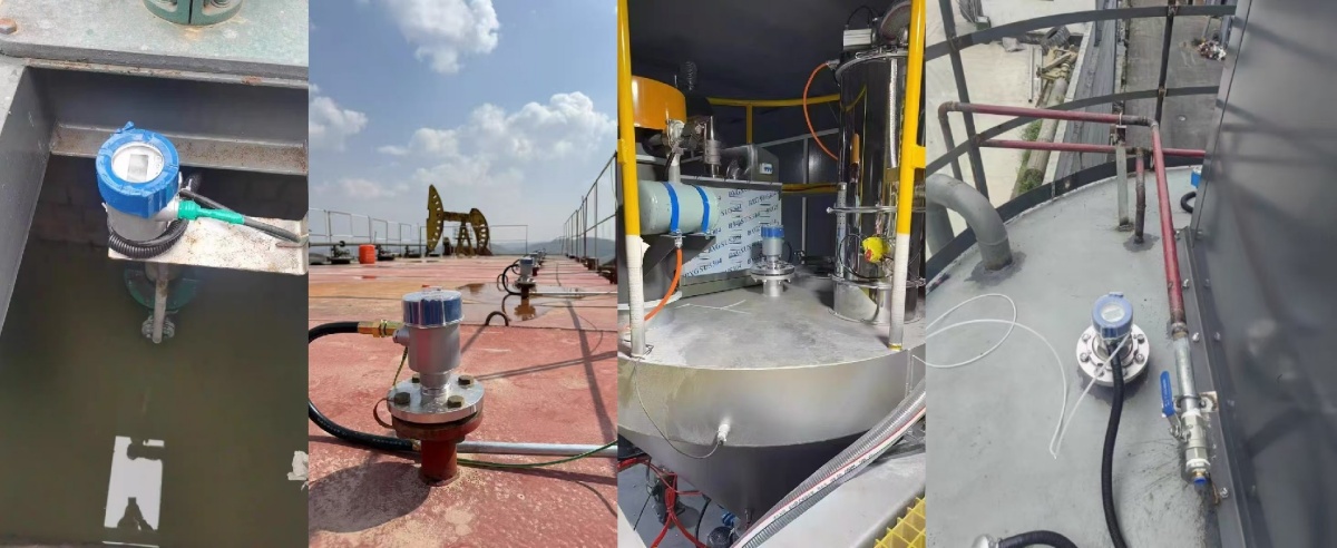
Application Scenarios: